 English

A practical step-by-step method for choosing materials that hold up in bending, assembly, and real environments
Flex material selection is a tradeoff exercise. The right stack-up is the one that meets the mechanical mission first, then satisfies electrical, thermal, environmental, and compliance constraints without creating cost or lead-time risk.
Use the seven steps below as a repeatable method for new designs, redesigns, and alternate qualification.
Step 1: Define the use case (measurable requirements)
Write requirements you can test. Avoid vague labels.
Mechanical
• Static vs dynamic flex
• Minimum bend radius (assembly + in-use)
• Estimated bend cycles / motion profile
• Thickness and stiffness targets
• High-stress zones (connectors, handling areas, transitions)
Electrical
• Frequency range / data rate
• Controlled impedance targets
• Loss budget
• Operating voltage + insulation resistance requirements
• EMI susceptibility or shielding constraints (if applicable)
Thermal
• Lead-free reflow profile + number of reflows
• Continuous operating temperature + peaks
• Thermal cycling expectations
Environmental
• Humidity/condensation exposure
• Chemical/solvent exposure (cleaning agents, fuels, sterilization, oils)
• UV exposure or outgassing constraints (if applicable)
Regulatory
• UL flammability needs (where applicable)
• Halogen-free requirements
• Documentation/traceability expectations
Supply chain + cost
• Cost target and acceptable alternates
• Lead-time sensitivity
• AVL constraints and regional sourcing needs
Deliverable: a one-page requirements brief you can attach to the design file.
Step 2: Mechanical screen (bend life and interface durability)
Mechanical performance is often the first elimination gate in flex, especially for dynamic applications or tight radii.
Confirm early
• Where strain is concentrated (bend zones, coverlay openings, stiffener edges, connector pads)
• Whether peel strength is a driver at exposed copper, edges, and connector areas
• Whether thickness/stiffness in the bend region is acceptable
Mechanical criteria to compare
• Fatigue resistance in bend zones
• Bond durability at interfaces
• Dimensional stability (registration, fine features)
• Crack initiation resistance under repeated flexing
Deliverable: a shortlist of constructions that are mechanically viable.
Step 3: Electrical screen (Dk/Df, loss, impedance stability, insulation)
With a mechanical shortlist in hand, evaluate electrical performance with emphasis on stability, not just nominal values.
Check
• Dk/Df at your operating frequency range (not only low-frequency datasheet values)
• Thickness tolerance and repeatability (drives impedance consistency)
• Loss drivers (dielectric + conductor) and variability risk
• Insulation resistance durability under humidity, temperature, and bias
Deliverable: an electrical pass/fail screen plus a ranked shortlist for SI needs.
Starting a flex PCB design?
Work with PICA’s engineering team to select the right materials, optimize stack-ups, and avoid reliability risks before production begins.
Step 4: Thermal screen (reflow survivability and thermal cycling)
Thermal stress often reveals bond-line weakness after assembly, even when early tests look fine.
Evaluate
• Number of lead-free reflows and peak temperatures
• Delamination/curling risk after repeated heat exposure
• Thermal cycling effects on interfaces (expansion/contraction stress)
• Electrical stability across temperature if controlled impedance is critical
Deliverable: confirmation the options survive assembly and expected cycling.
Step 5: Environmental screen (moisture, chemicals, UV, outgassing)
Environmental constraints can change the “best” answer quickly.
Confirm compatibility with
• Humidity and condensation risk (property drift + insulation stability)
• Chemical/solvent exposure from use or cleaning processes
• UV/outgassing constraints for sensitive applications (if relevant)
Deliverable: a final environmental pass/fail on the shortlist.
Step 6: Compliance screen (requirements + documentation)
Treat compliance as a selection input, not a last-minute checkbox.
Validate
• UL flammability expectations (where applicable)
• Halogen-free requirements
• Availability of declarations, traceability, and customer documentation
Deliverable: a compliance-ready shortlist with documentation paths.
Step 7: Supply chain + cost screen (robust, not just cheap)
Finish by selecting the option that is reliable and buildable under real lead times and sourcing constraints.
Supply chain checks
• Multi-source options for key materials
• Approved alternates and requalification impact
• Lead-time volatility and allocation risk
• Regional sourcing constraints
Cost checks
• Specialty materials where performance does not require them
• Opportunities to standardize material families across programs
• Design-for-cost adjustments that do not compromise reliability
Deliverable: final selection + an alternate strategy (Plan B).
Quick decision flow (use as an internal checklist)
• Dynamic flex or static flex?
• Tight radius or high cycles?
• Controlled impedance / higher frequency?
• Multiple lead-free reflows or heavy cycling?
• Humidity/chemicals/UV/outgassing constraints?
• Compliance + documentation requirements?
• Lead time, alternates, and cost risk acceptable?
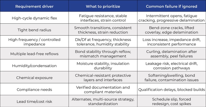
Comparison table: what each requirement pushes you toward
Learn more about PICA Manufacturing Solutions’ Flex PCB capabilities here.