In multilayer PCB fabrication, what connects copper layers together isn’t just glue—it’s carefully engineered dielectric materials that control signal integrity, insulation, and mechanical performance. Among these, prepreg plays a critical role, serving as both an adhesive and an electrical insulator between copper layers.
Whether you’re working on high-speed digital signals, RF layouts, or just stacking a simple 4-layer board, understanding how prepreg and dielectric cores work is key to building a reliable PCB.
What Are Prepreg and Core Materials?
In multilayer PCBs, prepreg (short for pre-impregnated) and core materials are the two main dielectric layers used to build up a stack:
• Core: A rigid layer of copper-clad laminate—essentially a double-sided PCB that acts as the central foundation of the board.
• Prepreg: A fiberglass weave that’s been partially impregnated with resin but not fully cured. When heated and pressed during lamination, it melts and bonds copper layers together while hardening into a solid dielectric.
These layers determine the thickness, dielectric constant (Dk), and loss tangent (Df) between copper planes—factors that are especially important in controlled impedance or high-speed designs.
Types of Prepreg and Dielectric Systems
Standard FR-4 Prepreg
• Material: Epoxy resin + woven glass (typically 106, 1080, 2116, 7628 glass styles)
• Best for: General-purpose digital, analog, and power boards
Most PCBs are built using standard FR-4 prepregs in combination with FR-4 cores. These materials offer a good balance of electrical insulation, mechanical strength, and thermal performance for the majority of applications.
Low-Dk / Low-Df Prepreg
• Material: Modified epoxy, BT epoxy, or hydrocarbon blends
• Best for: High-speed digital or RF applications
These materials are engineered to reduce signal loss and maintain consistent impedance at high frequencies. Ideal for DDR, SerDes, or RF layers above 1 GHz.
No-Flow or Low-Flow Prepreg
• Material: Resin systems with limited flow during lamination
• Best for: Rigid-flex PCBs and bonding stiffeners or coverlays
Used where you need adhesive bonding but can’t allow resin to spread into certain areas—like the flexible zones of a rigid-flex board.
Polyimide Prepreg
• Material: Polyimide resin + glass
• Best for: High-temperature or aerospace applications
Polyimide systems offer excellent thermal stability and mechanical toughness, but they come at a higher material and processing cost.
How Prepreg Affects PCB Performance
Engineers should consider the following when selecting prepreg:

Tip: Many board houses carry a limited selection of prepreg thicknesses and styles—choose values that align with common fabrication specs to avoid long lead times.
Ready to bring your PCB designs to life? Partner with PICA for expert engineering, fast turnaround, and reliable quality—every step of the way.
Prepreg and Core in a Real-World Stackup
Let’s say you’re building a 6-layer board:
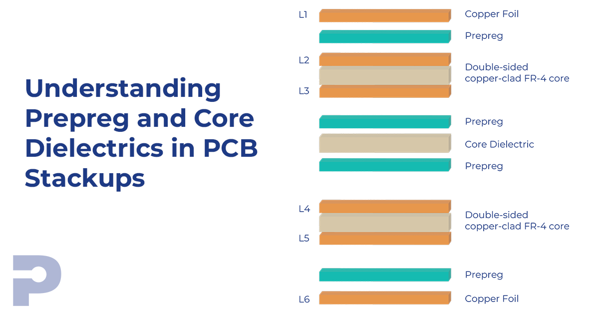
A 6-layer multilayer PCB can be constructed using two double-sided copper-clad cores with a central non-copper-clad core dielectric, flanked by prepreg layers, and copper foil on the external surfaces. The stack-up from top to bottom is as follows:
Cu foil (L1) / prepreg / Cu–Dielectric–Cu (L2–L3) / prepreg / central core dielectric / prepreg / Cu–Dielectric–Cu (L4–L5) / prepreg / Cu foil (L6)
In this construction:
• The two copper-clad cores provide four internal layers (L2–L5),• The central dielectric core, typically FR-4 or equivalent, offers mechanical stability and serves as a dimensional reference,
• Prepreg layers on both sides of the central core enable lamination bonding and electrical insulation,
• Outer copper foils form the external signal or plane layers (L1 and L6) after lamination.
This build supports high-density interconnects, stable mechanical properties, and controlled impedance routing essential for high-speed and mixed-signal designs.
Every interface between copper layers (except the central core) is held together by prepreg.

Common Prepreg Styles and Their Uses

Final Thoughts
Prepreg isn’t just filler—it’s a critical electrical and mechanical element in multilayer PCBs. The type and thickness of dielectric layers directly influence signal performance, layer adhesion, and thermal handling.
Choosing the right dielectric system means balancing electrical requirements, mechanical constraints, thermal environment, and manufacturing capability.
At PICA Manufacturing Solutions, we help customers design and fabricate multilayer stackups that meet both performance and manufacturability goals—whether that means tuning impedance with thin glass styles or optimizing flow control for rigid-flex applications.
