 English

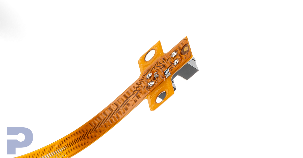
Close-up of a flex circuit with soldered connector pins and mounting holes
Through-hole technology mounts electronic components by inserting their leads or pins through holes in a printed circuit board. In a typical plated-through-hole assembly, solder connects the lead to the conductive hole barrel and associated pads. It remains useful for selected connectors, larger components, and assemblies whose physical design benefits from leads passing through the board.
How through hole assembly works
Components are inserted into the board, then soldered using a process suited to the design and production volume. Wave soldering exposes the intended underside features to molten solder. Selective soldering targets chosen connections. Manual soldering may suit prototypes, special parts, or accessible joints that need individual attention. Qualified manufacturers may support several of these processes. [1]
Insertion can be manual or automated, depending on the parts and production setup. The manufacturer must control the soldering operation and inspect the resulting connections against the specified requirements. A solder fillet visible on the outside does not, by itself, establish every condition inside the plated hole.
When through hole is a useful choice
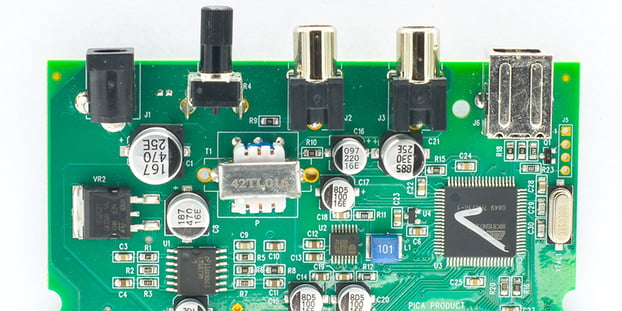
Consider it when the selected component is supplied in a through-hole package or when the mechanical design calls for pins that pass through the board. Connectors exposed to mating forces are a common reason to review this option. Larger magnetics and other substantial parts may also need a mounting approach that accounts for their weight and handling loads.
Mechanical support still needs engineering. A heavy part or a frequently connected cable can require brackets, fasteners, or other retention so the solder joints do not carry the entire load. Mounting style alone does not establish vibration performance, current capacity, or suitability for a harsh environment. Those depend on the complete component, board, and support design.
Need help choosing the right mounting approach for your PCB or flex circuit?
Our team can review your component requirements, mechanical loads, and assembly needs to help you make an informed design decision. Contact us to discuss your project.
Understand the space and process tradeoffs
Component holes and pads use board area and constrain routing. Surface mount packages generally offer more opportunity for compact layouts, while through-hole parts can provide accessible leads for some assembly and repair tasks. Serviceability should still be reviewed against the actual board construction and component spacing.
A mixed assembly may need both reflow and a separate through-hole soldering operation. [2] That affects process planning, tooling, and access. Before choosing a connector footprint, ask the assembler how the underside will be reached and whether nearby parts interfere with the planned soldering method.
Using through hole parts on flex
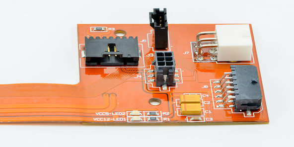
Through-hole components can be used on flex circuits, but insertion and connector loads need local support. A stiffener can stabilize the mounting area. Its placement, openings, and alignment must allow component insertion and access to the required solder features. Work with the fabricator on the mechanical details before releasing the design.
Show the intended bend region and the final installed shape on the engineering package. Review whether handling or operation could transfer movement into the component attachment area. For a flex circuit, the mounting decision and the bending requirement must be evaluated together.
Choose the method at the component level
A practical design often combines surface mount electronics with selected through-hole parts. Review the bill of materials, physical loads, board space, inspection access, and expected quantities with the manufacturer. Ask for feedback while package choices can still change. That discussion helps avoid a layout that meets the schematic but is difficult to assemble consistently.
Through-hole technology remains a useful engineering option when its physical construction serves the product. Use it deliberately, with the same attention to process control and verification applied to any other assembly method.
Sources
[1] IPC qualified assembly process capabilities
[2] Texas Instruments mixed assembly process flows