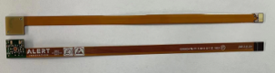
How to Protect Your Flex Circuits: Strain Relief and Tear Resistance Strategies
Flexible circuits—such as FFCs, FPCs, and rigid-flex assemblies—offer unparalleled design freedom in compact and dynamic electronic applications. However, their inherent flexibility makes them susceptible to mechanical stresses that can lead to failures like tearing, delamination, or conductor fatigue. Implementing effective strain relief and tear resistance measures is crucial to ensure the longevity and reliability of these circuits.
Understanding the Challenges
Flex circuits are often subjected to:
• Repeated flexing during operation or installation
• Mechanical stresses at connector interfaces
• Abrasion from handling or environmental factors
• Stress concentrations at sharp corners or cutouts
Without proper design considerations, these factors can compromise the mechanical integrity of the circuit.
Strain Relief Techniques
1. Stiffeners
Adding stiffeners reinforces specific areas of the flex circuit, providing mechanical support and reducing stress on solder joints and connectors.
• Materials: Commonly used materials include FR4 and polyimide.
• Placement: Typically applied under connectors or components to prevent flexing in those regions.
• Design Tip: Ensure the stiffener overlaps the coverlay by at least 0.030" to effectively distribute stress.

Applying a bead of flexible adhesive (such as epoxy or silicone) at the transition between rigid and flexible sections can mitigate stress concentrations.
• Application: The fillet should have a width of 1–2 mm and be applied to both sides of the flex layer at the transition point.
• Consideration: Maintain a minimum height difference of 0.010" between the rigid and flex areas to accommodate the fillet without interfering with assembly processes.

• Guideline: For single-layer flex circuits, the minimum bend radius should be at least six times the thickness of the circuit. For multilayer circuits, this factor increases.
• Single-sided circuits: Maintain a bend radius of 3 to 6 times the circuit thickness.
• Double-sided circuits: A bend radius of 6 to 10 times the circuit thickness is recommended.
Protect Your Flex Circuits from Failure
Learn how to prevent tearing, delamination, and fatigue with smart design choices like stiffeners, fillets, and tear stops.
Enhancing Tear Resistance
To increase tear resistance, certain design features can be incorporated:
1. Large Radii in Corners: Prevents stress concentration which can lead to tearing.2. Embedded Glass Cloth: Provides structural integrity and resistance to tearing.
3. Recessed Slot and Hole in Slit: Reduces the likelihood of tear initiation.
4. Drilled Hole at Corner: Disperses stress that can cause tears at vulnerable points.
5. Embedded Aramid Fiber: Offers high strength and resistance to tearing.
6. Extra Copper in Corners: Strengthens corner areas which are prone to higher stress.
Best Practices for Handling and Installation
• Secure Mounting: Use appropriate mounting hardware to prevent movement and reduce mechanical stress.
• Proper Routing: Design the flex circuit path to minimize sharp bends and twists, use uniform trace width and spacing across the bend area
• Use RA copper: RA copper is more adaptable to repeated bending than ED copper.
Verify the effectiveness of the design
FPC can conduct a series of reliability tests to verify the correctness of the design, such as Bending test, Peel Strength test, Flexural Endurance test.
Conclusion
Implementing effective strain relief and tear resistance strategies is essential for the durability and reliability of flexible circuits. By incorporating design features such as stiffeners, strain relief fillets, proper bend radii, and tear stops, engineers can significantly enhance the mechanical performance of FFCs, FPCs, and rigid-flex assemblies.
At PICA Manufacturing Solutions, we specialize in designing and manufacturing robust flexible circuit solutions tailored to your application's specific needs. Our expertise ensures that your designs not only meet electrical requirements but also withstand mechanical stresses throughout their lifecycle. We also can support sufficient testing to verify the FPC circuit design.