Part 1: High-Temperature Flex Circuit Design – Engineering for Heat Resistance
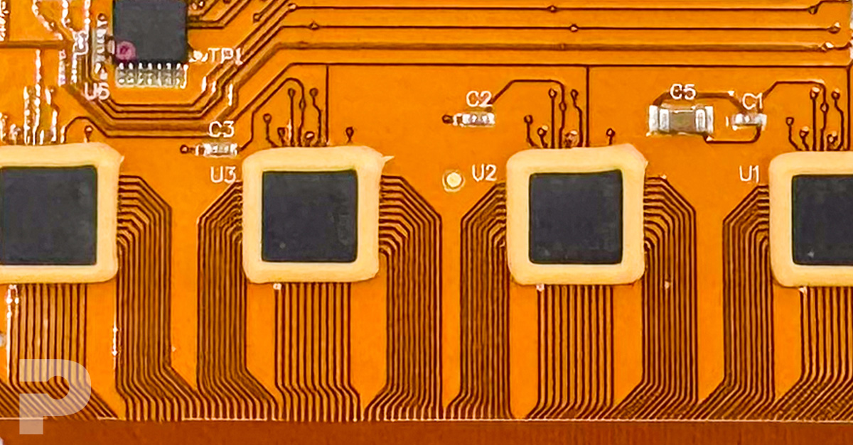
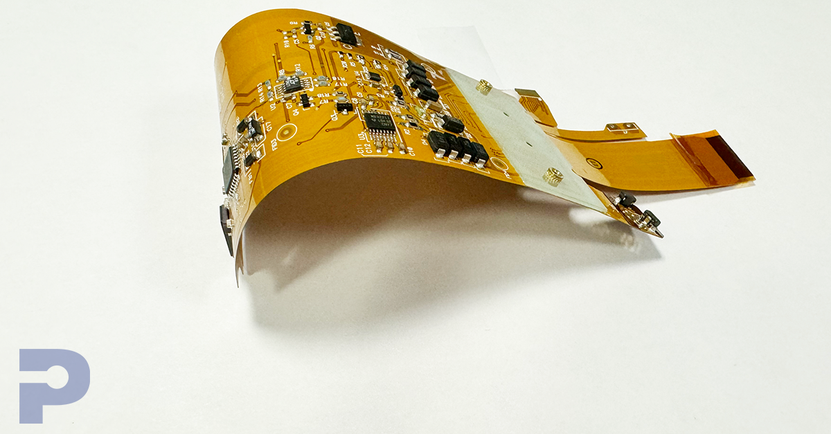
In aerospace, automotive, industrial, and oil & gas environments, heat is an unavoidable challenge. Flexible printed circuit boards (FPCBs) deployed in these conditions must maintain performance under constant thermal load, thermal cycling, and occasional temperature spikes. Designing a high-temperature flex PCB is not only about choosing the right materials, it's also about engineering a system that maintains integrity and reliability under prolonged stress. Here’s how to design FPCs that can stand the heat.
1. Choosing High-Temp Base Materials
Polyimide is the industry standard dielectric for high-temperature flex PCBs, offering short-term endurance up to 260°C and sustained performance around 200°C. Adhesiveless polyimide constructions reduce the chance of delamination while enhancing dimensional stability during thermal cycling. For mission-critical designs, alternatives like PTFE or LCP (liquid crystal polymer) substrates may be selected for their superior RF and thermal stability. These materials can handle both high heat and electrical insulation requirements.
2. Thermal-Resistant Adhesives and Coverlays
As temperatures rise, adhesives become a common point of failure. PICA selects thermal-set adhesives such as modified acrylics and high-temperature epoxies, which provide both adhesion and durability at elevated temps. Coverlays must be engineered to resist blistering and curling—especially during high-temp reflow processes. Thermal-set polyimide coverlays, carefully laminated and cured, ensure the board retains mechanical protection and electrical insulation even after multiple reflow cycles.
3. Reinforcing with Heat-Sink Layers or Thermal Reliefs
In high-current or thermally intense regions, heat-sinking techniques help disperse thermal energy. Metal stiffeners, copper planes, or even embedded heat-spreading layers are used to redirect and dissipate excess heat. PICA also incorporates thermal relief designs around solder joints and vias, which protect delicate areas from becoming thermal chokepoints during assembly or operation.
Talk to an engineer about RA copper, coverlays, bend radii, and strain-relief—so your design survives real-world conditions.
4. Controlled Impedance at High Temps
High-speed flex circuits operating in elevated temperatures are prone to impedance drift due to material expansion and dielectric constant variation. To counter this, PICA uses predictive modeling and tight process controls to account for high-temperature operation. Material stack-ups are tested to ensure consistent impedance across a wide thermal range, ensuring signal integrity is not compromised under stress.
5. Soldering & Assembly Considerations
High-temp FPCs must withstand repeated soldering processes such as reflow (up to 260°C) without substrate warping or adhesive degradation. Material and adhesive choices are validated to ensure they remain intact and dimensionally stable throughout assembly. PICA follows IPC-6013 Class 3 guidelines and stress tests each stackup in conditions that mimic the production environment.
Conclusion:
Designing for high temperatures demands an integrated approach—leveraging advanced materials, mechanical reinforcement, and signal integrity modeling. At PICA, we combine these techniques to deliver flex PCBs that perform in the world’s toughest thermal conditions.
Part 2: Low-Temperature Flex Circuit Design – Surviving the Cold
Flex PCBs don’t just face heat—they also have to survive the cold. In aerospace, defense, cryogenic research, and outdoor IoT deployments, electronic systems must perform in sub-zero temperatures, sometimes dipping below -70°C. Cold conditions bring unique challenges: materials become brittle, adhesion weakens, and electrical performance can degrade. This part of our series focuses on how to design flex circuits that remain dependable even in the harshest cold environments.
1. Material Selection for Cold Resilience
Most standard polyimide substrates become stiffer and more brittle as temperatures decrease. PICA addresses this by using low-temperature polyimides, elastomeric adhesives, or LCP (liquid crystal polymer) substrates, which retain flexibility at cryogenic temperatures. Low glass transition temperature (Tg) materials are preferred to avoid cracking and to ensure flexibility is retained throughout the operational range.
2. Avoiding Brittle Fracture & Cracking
Cold environments increase the likelihood of mechanical failure due to material shrinkage and reduced ductility. To counteract this, PICA uses rolled annealed (RA) copper instead of electro-deposited (ED) copper, as RA copper maintains flexibility and is less prone to microcracks. Designs also incorporate larger bend radii and avoid tight corners to reduce stress on conductors.
3. Thermal Cycling Resistance
One of the harshest realities of cold-weather electronics is thermal cycling—going from warm to freezing and back again. This expansion and contraction cycle stresses the bond between layers. PICA’s engineers carefully select materials with matched coefficients of thermal expansion (CTEs) and design stackups that can flex with the system, rather than against it. Special encapsulation methods are applied to protect exposed conductors and interfaces.
4. Conductivity and Dielectric Stability in the Cold
Electrical resistance increases as temperature drops, and the dielectric constant of insulating materials can shift unpredictably. For low-temp designs, PICA recommends wider traces or redundant paths for critical signals, along with materials known to maintain stable dielectric performance even below freezing. This ensures power delivery and signal fidelity are not compromised by the cold.
5. Testing for Freeze Performance
Design validation is critical when electronics are exposed to cold. PICA uses environmental chambers to simulate low-temperature conditions, often combining thermal cycling with mechanical flexing to verify reliability. We adhere to IPC-TM-650 test standards and our own rigorous protocols to ensure adhesion strength, material integrity, and electrical continuity are preserved.
Conclusion:
Cold may slow down most materials—but not a well-engineered flex circuit. By anticipating brittleness, shrinkage, and conductivity shifts, PICA designs flex PCBs that deliver performance and reliability in sub-zero conditions, from the stratosphere to the cryolab.
